The Ventilated Curtain Walls (VCWs) System
A ventilated curtain wall (VCW) is a façade system composed of several layers, in which the supporting external wall is provided with a layer (cladding) that offers protection against the weather. The cladding can be made from a wide variety of materials: ceramic, metal, fiber cement, composite panels, natural stone, etc. The substructure attaches this façade cladding to the solid outer wall of a building while leaving a gap between the two.
Ventilated Curtain Walls are acknowledged as one of the most sustainable, cost-effective, and technologically advanced facade systems. On top of their outstanding structural and physical advantages, VCWs offer architects a virtually unlimited range of possibilities for creating striking designs.
Area of use
VCW opens up many possibilities for innovative architectonic design and also provides the building with an aesthetic, structurally safe and essentially maintenance-free facade.
New buildings are fitted with exterior cladding that meets the applicable structural requirements. For buildings undergoing refurbishment or modernization, the architectonic improvement go hand-in-hand with a significant reduction in operating and maintenance costs.
VCW fulfils all the requirements of modern facade construction from prestigious administrative buildings and attractive production to large residential houses.
How do ventilated façade systems work?
Ventilated facade system also known as double-skin facades or rain-screens, can also assist in protecting buildings against the combined action of wind and rain by counterbalancing the effects of water beating on walls and keeping the building dry.
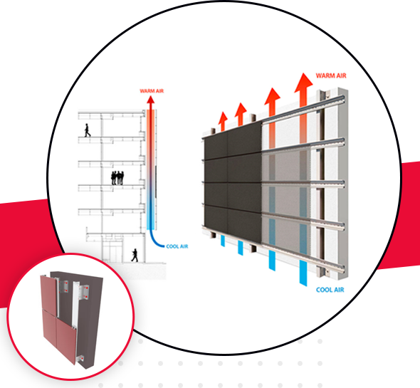
At its most basic, a ventilated facade system consists of two layers of different facades which are separated by an air cavity. This cavity prevents rainwater from penetrating and diffuses water vapour from the inside to the outside. While the external cladding serves to provide the majority of rain and wind protection, the air corridor between the support structure and the external cladding plays a major role in the ventilated facade system. A naturally ventilated facade results in a temperature difference between the face of the cladding panel and the air cavity behind. This in turn creates a variation in air density and causes air to flow upwards within the cavity according to the stack effect. The airflow transports heat from the cavity out through high level exhausts, aiding convection drying of any residual amounts of moisture that have accumulated within the air cavity.
Benefits of ventilated facade systems
The system provides three main benefits for buildings:
Thermal
Significant reductions in HVAC reliance through:
• A reduction in the amount of heat that buildings absorb in hot weather conditions from the partial reflection of solar radiation by the outside façade, and the naturally ventilated air cavity.
• In cold weather conditions ventilated walls retain heat, resulting in a lower reliance on heating. HVAC electricity consumption typically accounts for around 40% of total building consumption. Research has shown ventilated facades systems can easily achieve savings of about 30% on energy consumption.
Acoustic
Ventilated façade systems provide an increase in the reflection of external noise, an average reduction of up to 8dB. With the primary external noise sources affecting buildings being road traffic noise, a reduction of this level can greatly improve occupant comfort.
Structural
In addition a secondary façade provides protection against wind and rain. The natural bottom-to-top airflow through the cavity assists in eliminating moisture accumulation on the facades, preventing mould and water ingress, helping to prolong the structural integrity and ultimately the lifespan of a building.
Structural components of the VCW façade system
Façade anchors approved by the building authorities must be used to anchor the VCW to the supporting external wall. The optimum anchors are selected for use in each project based on considerations such as materials used in the construction of the supporting external wall and prevailing loads
Insulation
Suitable insulation materials:
Only mineral wool materials may be used for the insulation of VCW. These must be non-flammable and absorb very little moisture.
The insulation materials must be stored dry and then laid and joined together in a single layer on the supporting wall. The insulation panels must be installed in such a way that there is no gap between the surface of the wall and the insulating layer. This ensures that no current of cold outdoor air can circulate behind the insulation. The joints between the insulation panels must be pushed firmly together to ensure a tight seal. Connections to the substructure, e.g. brackets, must be installed with no gaps. The fleece lamination must always be to the outside.
Fastening
Mineral wool insulation panels are always fixed in place mechanically. They are fastened using insulation brackets, which have a limiter to ensure the insulating material retains its full thickness at the fastening point.
Substructure
The substructure transmits the load of the cladding itself and the wind load to the enclosing external wall. Metal substructures are generally used as these can compensate for tolerances in the shell construction. Most systems consist of a two-part construction, which is fastened to the supporting external wall using anchors. This base construction is aligned plumb and flush and acts as a support for installing a variety of facade cladding materials.
The substructure system must be designed in such a way that materials used can expand due to temperature changes without creating stresses in the structure.
For example, when using aluminium profiles with a length of approx. 3 m, an expansion of 5mm must be taken into account (temperature range -20° C to 80° C).
So-called fix point / sliding point structures are often used for this purpose.
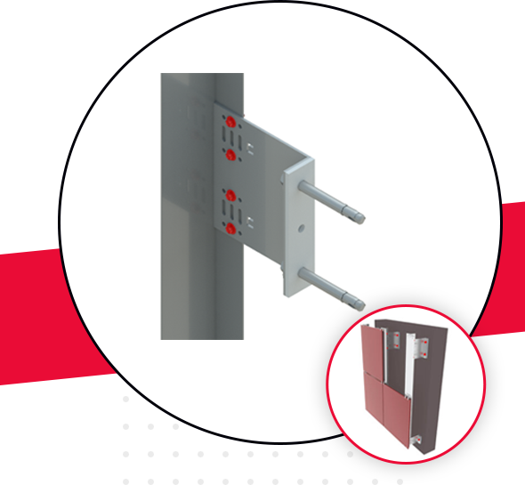
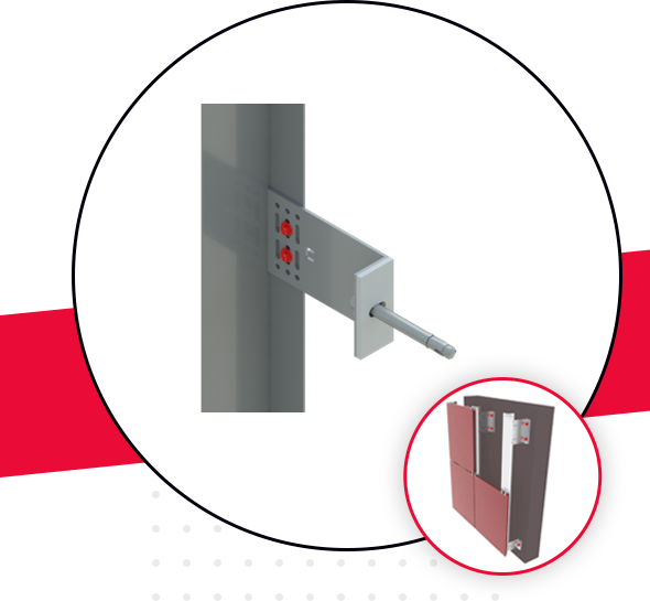
The bracket used has the following functions::
- acts as a fix point for screwing the profiles into position in the round hole – the profile is fixed, transmission of own weight and wind loads
- acts as a sliding point for screwing the profiles into position in the slot hole – the profile slides in the slot holes, transmission of wind loads only


